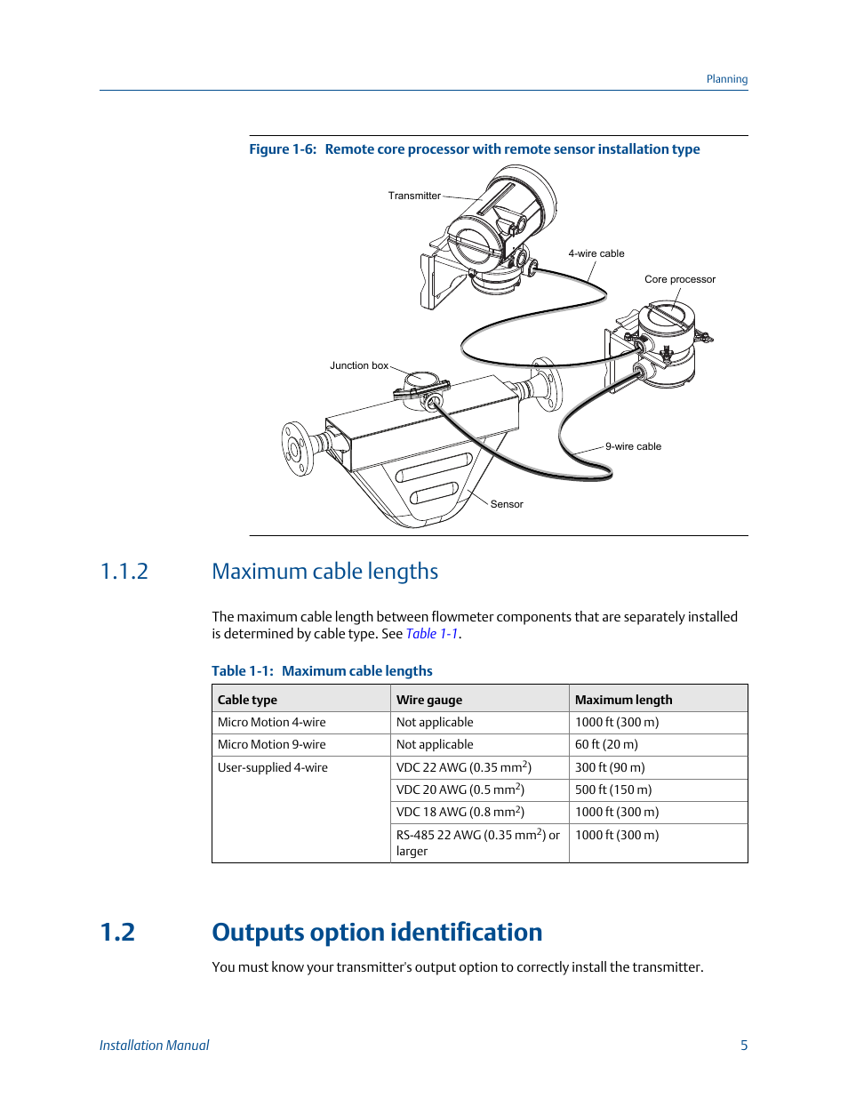
Micro Motion ELITE Coriolis Flow and Density Sensors. Instructions in the transmitter installation manual for power and signal wiring. Micro Motion 9-wire 9739 MVD transmitter 1000 ft (300 m) All other MVD transmitters 60 ft (20 m). 2 Micro Motion® Model 1700 and 2700 Transmitters Before You Begin 1.3 Flowmeter components The Model 1700 or 2700 transmitter is one component in your Micro Motion flowmeter. Other major components include:.The sensor, which provides measurement functions.The core processor, which provides memory and processing functions.
Integral installation
Figure 1-1:
Transmitter
Sensor
Micro Motion Transmitter Manual
•
High-temperature flexible conduit – Some high-temperature meters come
preinstalled with a flexible conduit between the sensor and the transmitter. You do
not have to connect any wires between the transmitter and the sensor, but you do
need to mount the electronics separately and connect power and I/O wiring to the
transmitter.
High-temperature flexible conduit installation

Figure 1-2:
High-temperature flexible conduit installations use the same installation
instructions as 4-wire remote installations, except that the distance between the
sensor and the electronics is limited by the length of the flexible conduit.
•
Micro Motion 1700 Transmitter User Manual Download
4-wire remote – The transmitter is installed remotely from the sensor. You need to
mount the transmitter separately from the sensor, connect a 4-wire cable between
the transmitter and sensor, and connect power and I/O wiring to the transmitter.
Planning
2
Micro Motion
®
Model 1700 and 2700

The transmitter's model number is on a tag on the side of the transmitter. You can use the
model number to determine the transmitter's output option. The first four characters are
the transmitter type. The fifth character is the installation type. The eighth character is the
output option. The remaining characters are not relevant to transmitter installation.
Model code identification
Figure 1-7:
Transmitter type
Micro Motion 1700 Configuration Manual
Installation type
Output option
Installation types for Model 1700 and Model 2700 transmitters
Table 1-2:
Letter
Description
R
Remote mount 4-wire
I
Integral
C
Remote mount 9-wire (painted aluminum housing)
B
Remote core processor with remote transmitter
M
Remote mount 4-wire (stainless steel housing)
P
Remote mount 9-wire (stainless steel housing)
Output options for Model 1700 and Model 2700 transmitters
Table 1-3:
Letter
Description
A
Analog outputs – one mA, one frequency, one RS-485
B
Configurable I/O channels (default configuration of two mA, one frequency)
C
Configurable I/O channels (custom configuration )
D

Intrinsically safe analog outputs – two mA, one frequency/discrete
E
Intrinsically safe Foundation fieldbus H1 with standard function blocks
G
PROFIBUS-PA
N
Non-incendive Foundation fieldbus H1 with standard function blcoks
2
WirelessHART – one mA, one frequency, one RS-485
3
WirelessHART – one mA, two configurable I/O channels (custom configura-
tion)
4
Intrinsically safe WirelessHART – two mA, one frequency
Planning
6
Micro Motion 1700 Transmitter Manual
Micro Motion
®
Model 1700 and 2700